| Title - $10.99 | |
|
View |
Procedure of De Energize QE300 Magnet
Prepare the magnet:
Prepare Power Stick
B1 ´C B5 short B10 ´C A1 100 Ohm ---- Common to Main Heater B10 ´C A2 100 Ohm ----Common to Y Heater B10 ´C A4 100 Ohm ---- Common to Z3 Heater B10 ´C A3 100 Ohm ---- Common to X Heater
Prepare the following Tools:
Start to De-engergize the magnet. If started, there is no way to stop it !!!
The following Guide is from Joe BAhnan: The other two wires coming out of the 10 pin connector are pot taps for measuring DC voltage. HereÀ₤s a quick guideline:
1. Make sure you have 80% Lhe. 2. Connect diodes to energizing lead. 3. Pull shorting plug and insert energizing lead into NMR. Caution of cold gases boiling off when inserting room temp e-lead. 4. Connect the 2 ten pin connectors to top of e-lead noting plug "A" and "B". Connect the two wires coming from connector B to a volt meter set up for DC. 5. Connect power supply. 6. Remove any carbon burst discs if any are present as not to burst in a quench. 7. Increase power supply voltage until main switch opens; when the volt meter jumps from zero to about 1.2VDC the switch has opened and the magnet is de-energizing. 8. Allow the volt meter to run down to zero ( about 3-4 hours usually). 9. Confirm field is gone with small bit of ferrous material before removing diodes and/or lead.
Call John Davidson or I with any questions and please be safe. Joe Bahnan cell 908 578 9299.
This note is from Oxford Magnet Manual:
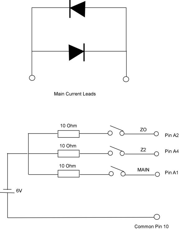
The magnet may be discharged by connecting a pair of diodes across the terminals as shown in the following figure. Switch on the Z0 and Z2 shim coil switch heaters and then the main coil heater. The magnet will discharge at a rate determined by the forward voltage drop of the diodes. Care should therefore be taken no to disconnect the diodes before the discharge is complete. The diodes must be capable of carrying the full operating current of the magnet and must be fixed to an adequate heat-sink.
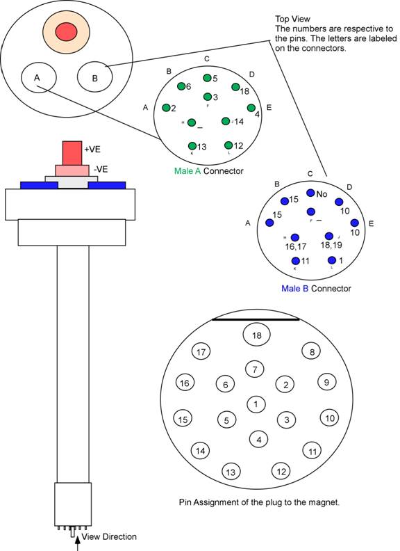
Pins Plug 1 ´Ê B10 (L) Heater and resistor Common 2 ´Ê A1 Main 3 ´Ê A6 Z0 4 ´Ê A5 Z1 5 ´Ê A3 X 6 ´Ê A2 Y 7 ´Ê ZX 8 ´Ê B8 Main Coil Start 9 ´Ê B8 Maint Coil Start 10 ´Ê B4 B5 Shims (+Ve) current input 11 ´Ê B9 ZY 12 ´Ê A10 XY 13 ´Ê A9 R2 14 ´Ê A8 15 ´Ê B2 Shims (-Ve) Current Rrturn 16 ´Ê B7 Main Coil End 17 ´Ê B7 Main Coil End 18 ´Ê A4 Z3
Note: 1 -18 are the pin numbers. The first letter is for the connector A or B. The second number is A=1, B=2, C=3, D=4, E=5, F=6, H =7, J=8, K=9 and L=10.
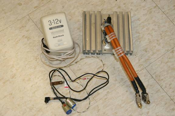
Diodes for de-energize the magnet. Discontinued 150KR80A ,replaced by 45LR120D.
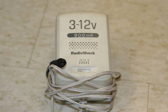
Adjustable Power supply. There are two pins to connect the two plugs.
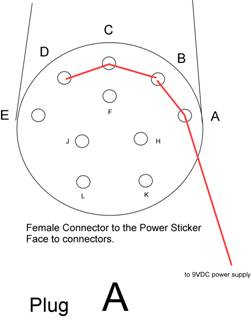
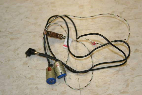
Plugs, Plug A connect to A port and Plug B connect B port on the power Lead.
7/8/2009 DE-energize ALOX 300 Magnet (Mercury 300) 1. Liquid helium is full, Liquid ntrogen 80% 2. Power leads (from John Davidson) a. remove the left colume (the right one is for LHe refilling); b. Unplug the shorting plug; c. insert the power lead. make sure it seat well. d. connect the diodes pack, connect the A and B plug. Plug the power supply (start at 3 VDC). then increase to 6 VDC, the volemeter jump from 0.0000Volts to 0.9096, then decreases. The de-energization started. about one hour, it goes to about 0.0050VDC. Unplug the power lead and replace the shorting plug. Use N2 gas to release vacuum. until the the red plate drop.
|