INOVA600:9/15/2003-9/22/2003
Problem: Setup H1 and C13 by using standard parameters, there is no signal. Just noise line.
Troubleshooting:
1. Use scope to check channel A input pulse: (pw 40us, tpwr=56, d1=0.5 aq=0.5 gain=0)
There is an input pulse.
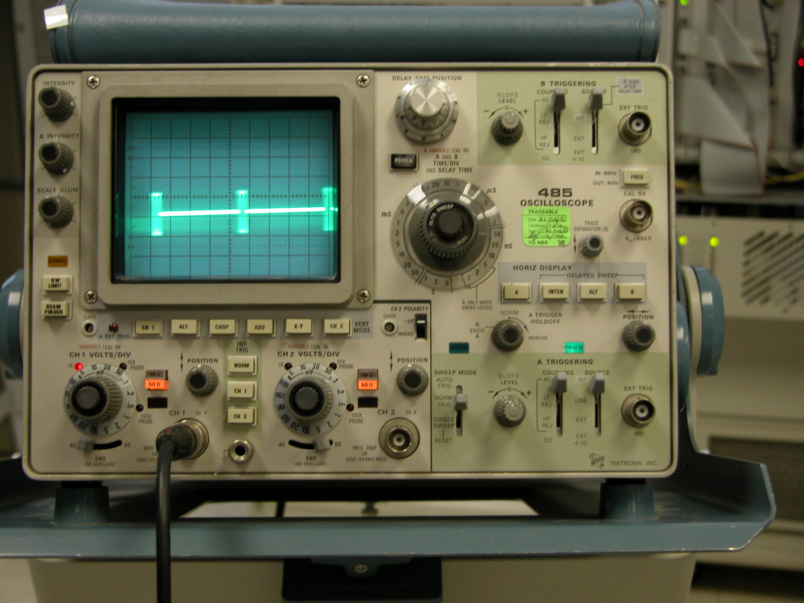
2. Use scope with a 30dB attenuators to check channel A output. There is no output pulse.
Amplifier problem!!!!!!!!!!!!!!!!!?
Take it out and check it.
?
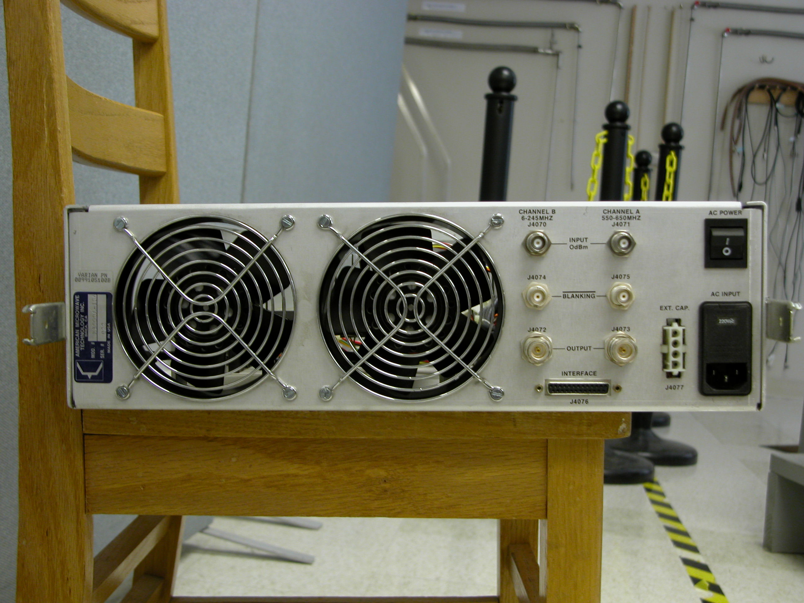
BNC connectors: top right channel A and top left channel B? (INPUT low power pulse > 1 Volts)
N-type connect: bottom right H1 pulse output, left X pulse output.
25 pin connector to the front Amp & Rout board (exchangeable with other inova system)
Power supply 220Volts. Use the console power supply!!!!!!!!!!!!!!!!!!!!!!!!!!!!!!!!!!!
25 pin ribbon cable connects to the top of the board.
?
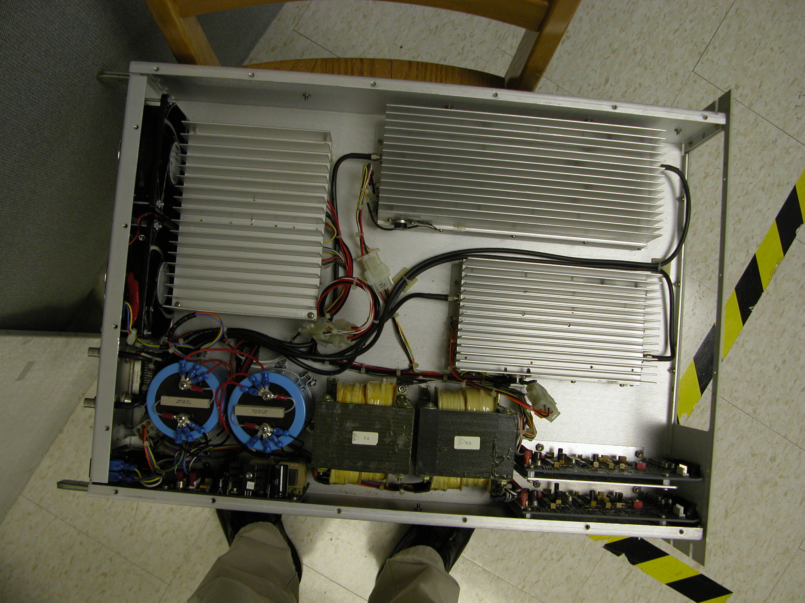
Step 2:? Open the amplifier box.
1. Measure the 28 VDC to the amplifier (High Band). No voltage! It is suggested that the power supply has problem.
2. Measure the power supply, from the two big capacitor, there is +66V.
3. Check the heatsink assambly (Aluminum box one left) There are two connectors. Unplug them.
There is a snaper U602S (it is overheat resistant. It is OPEN at normal operation, if it is overheated, it will close and cut off the power
supply to the amplifier). Use voltmeter to measure it. It is OPEN. But no 28Volts output.
http://www.asahikeiki.com.sg/US602.htm

?
Problem:
1. The transistors(MJ15001NPN) on this board are bad. MJ15001 could be purchased from Electronic distribution stores.
http://www.onsemi.com/site/products/summary/0,4450,MJ15001,00.html
| Parametric Table | ||||||||||||||||||||||||||||||
|
||||||||||||||||||||||||||||||
| Orderable Devices | ||||||||||||||||||||||||||||||
|
||||||||||||||||||||||||||||||
|
||||||||||||||||||||||||||||||
???????????????
?
2. The blanking signals are not correct.
These small wires are blanking signals from the amplifier control board.
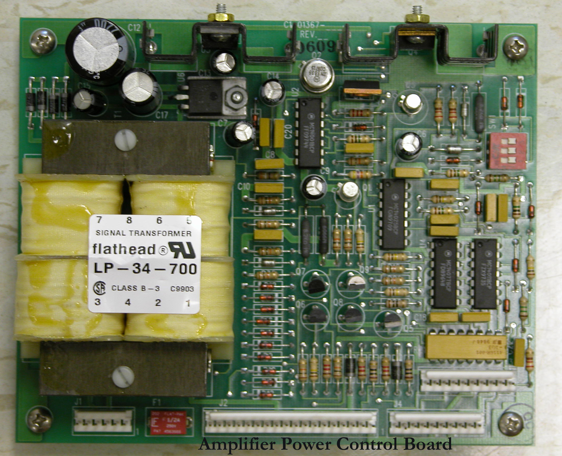
There is no diagram from AMT or Varian. It is very hard to trace the signal without diagram.
However, it could be purchase from AMT for about $450/each.
$$$$$$$$$$$$$$$$$$$$$$$$$$$$$$$$$$$$$$$$$$$$$$$$$$$$$$$$$$$$$$$$$$$$
After replace the amplifier control board, 28V is restored. It is working.