|
|
|
|
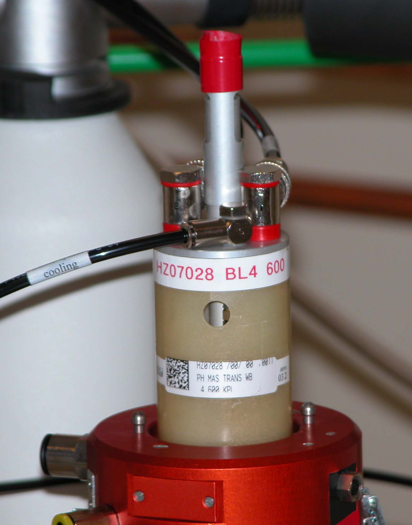
HRMAS upstack installation. HRMAS uses different stack to load samples. Upstack of the magnet: This is for normal solid state NMR operation. There are three gas inputs. Before install HRMAS probe, these upstacks should be removed. First eject the sample from the HXY probe. Unplug the air hosts and remove the inner stack. It is about 4 feet long. see the picture.
From the top: inner stack, outer stack for CPMAS probe. From Bottom: Inner stack, Outer stack for HRMAS probe. After remove the inner stack, then remove the outer stack. Install the outer stack for HRMAS, then install the HRMAS probe. Insert the inner stack, make sure it is coupled with the probe.
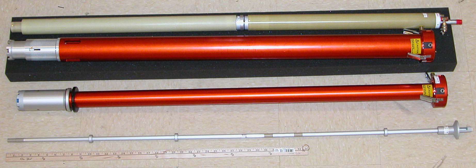
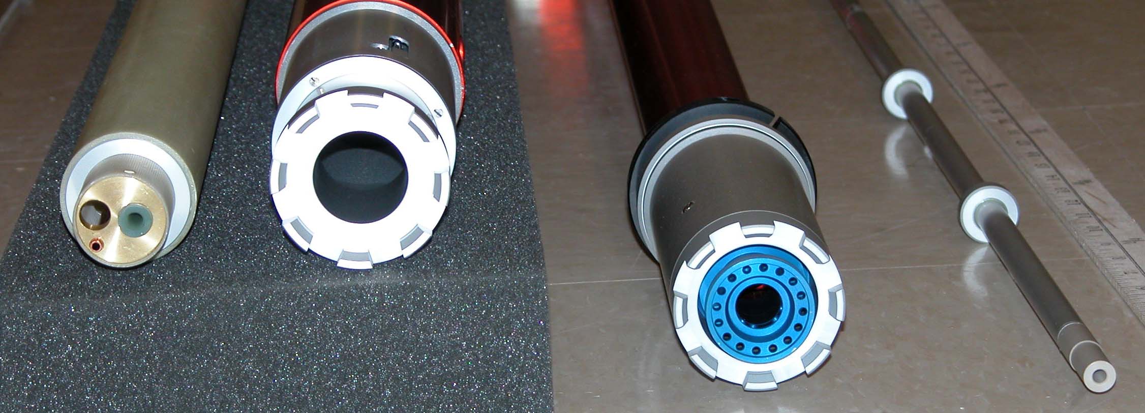
Here is the picture of the stacks: from left: CPMAS probe inner stack, CPMAS probe outer stack, HRMAS outer stack and HRMAS inner stack.
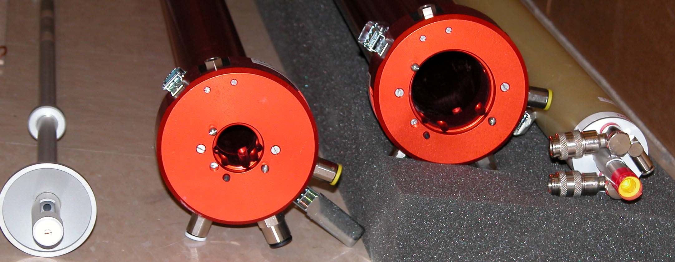
Bottom view: from left: HRMAS probe inner and outer stack; CPMAS probe outer and inner stack.
Top view of stacks.
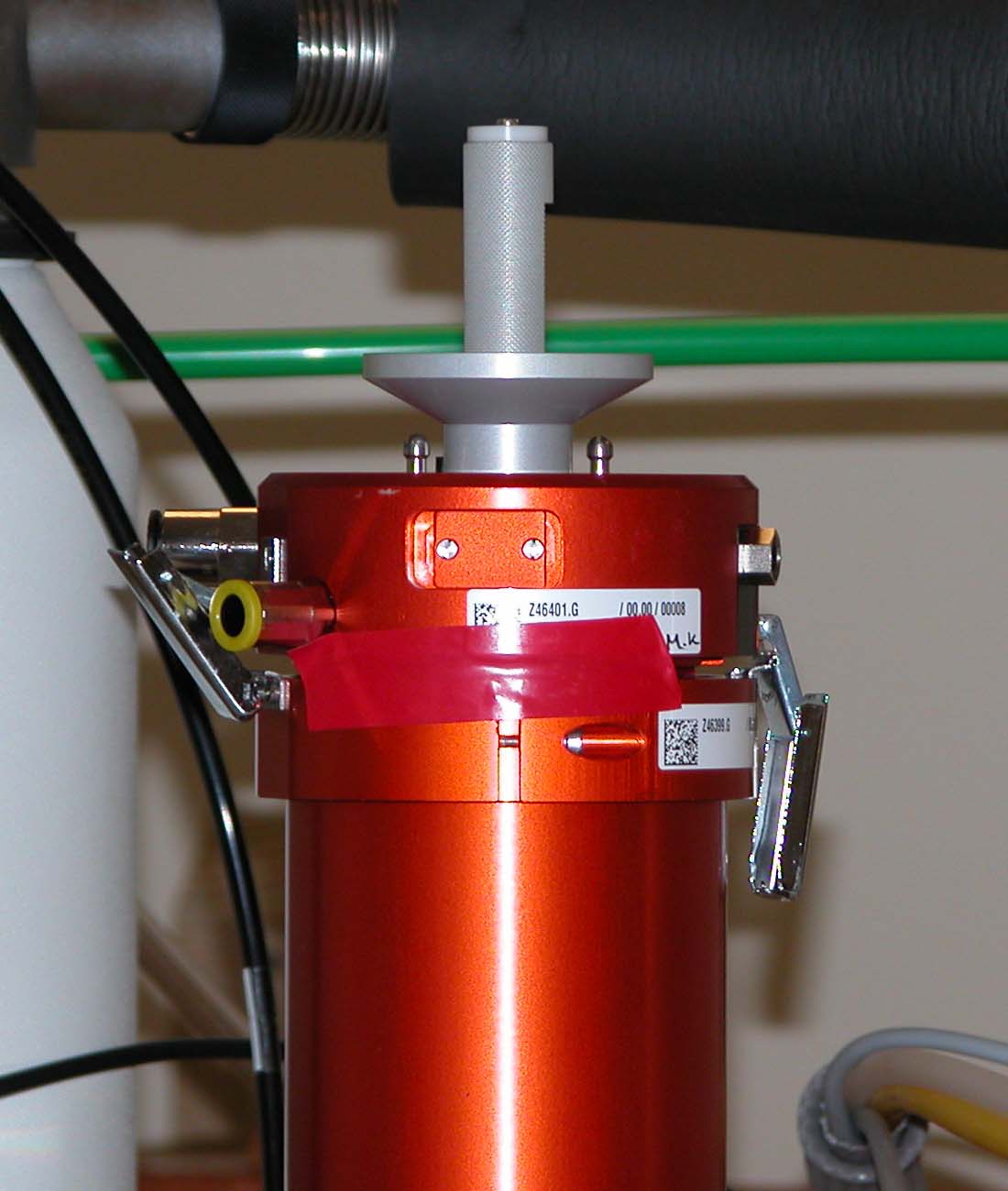
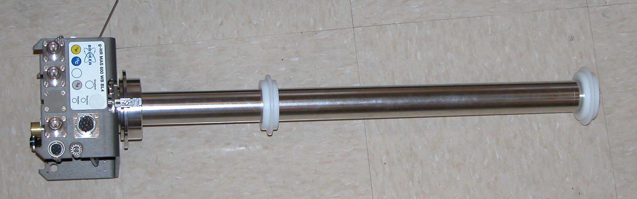
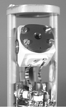
HRMAS probe. The white rings are suporters. Align the probe with the Y-shim gradient direction for easy shimming process.
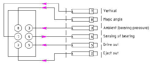
MAS stator in magic angle position. The HR-MAS probes have been designed to perform solution type experiments, while spinning the sample at the magic angle. The probes are either doubly tuned (e.g. 1H and 13C) or triply tuned (e.g. 1H, 13C and 15N), in addition to a 2H lock channel. All three (or four) channels are operating via a single NMR transmit/receive solenoid coil located inside the MAS turbine (see the picture above). The probes are capable of performing either direct or indirect detection experiments. Properties of the HR-MAS probes include: 1. MAS at spinning rates of up to 16 kHz for 4 mm o.d. Zirconia rotors for liquid or liquid-like samples and up to 6 kHz with spherical volume PTFE or Kel-F inserts; 2. Sample insertion/ejection without removal of the probe (up to 600 MHz); 3. Magic angle adjustment with micrometer screw at probe bottom; 4. Built-in heater/dewar and thermocouple for VT operation from -20°C to +70°C; 5. Optical spin rate counter with trigger signal output for rotor synchronized experiments; 6. Automatic insert and eject of the sample using the MAS sample changer. (Not available at Emory) Tubing connection: There is an additional set of tubings for above application. All the number labeled on the tube, probe and back of the MAS control unit.
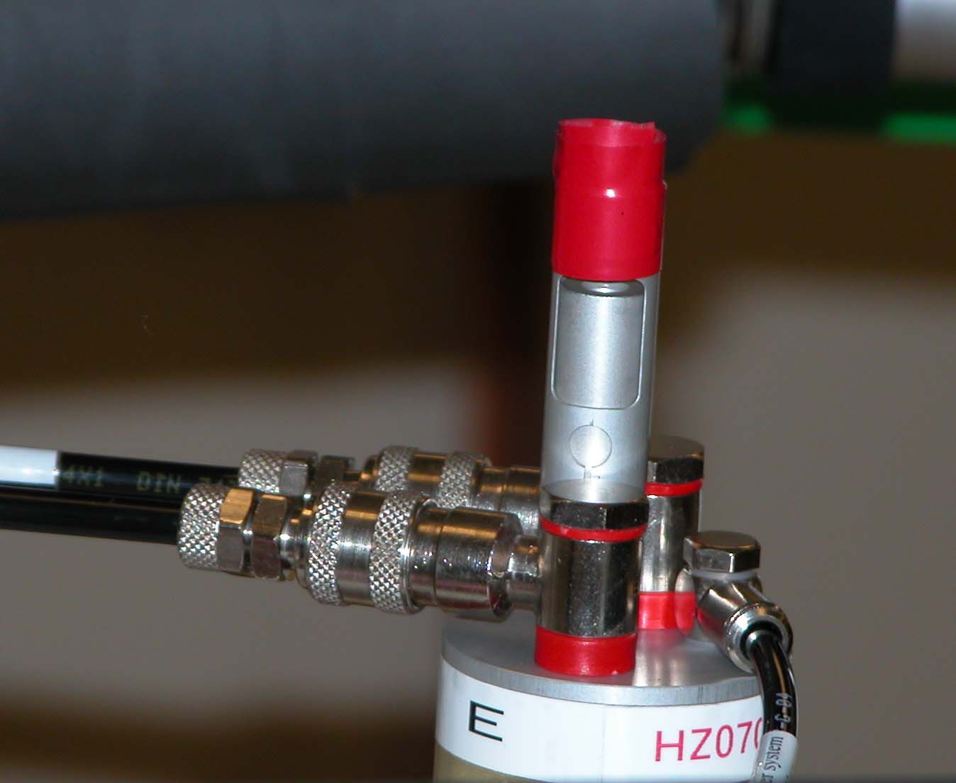
RF Cable Connection a. Connect the X-channel of the probe to the X-BB HPPR preamplifier using a proton reject or a low pass filter; b. Connect the 1H-channel of the probe to the proton using a proton band pass filter;c. Connect the 2H-lock channel of the probe with the lock preamplifier;Use low power amplifiers!!!!!!!!!!!!!!!!!!!!!!!!!!!!!! Picture of cable connections: |
|
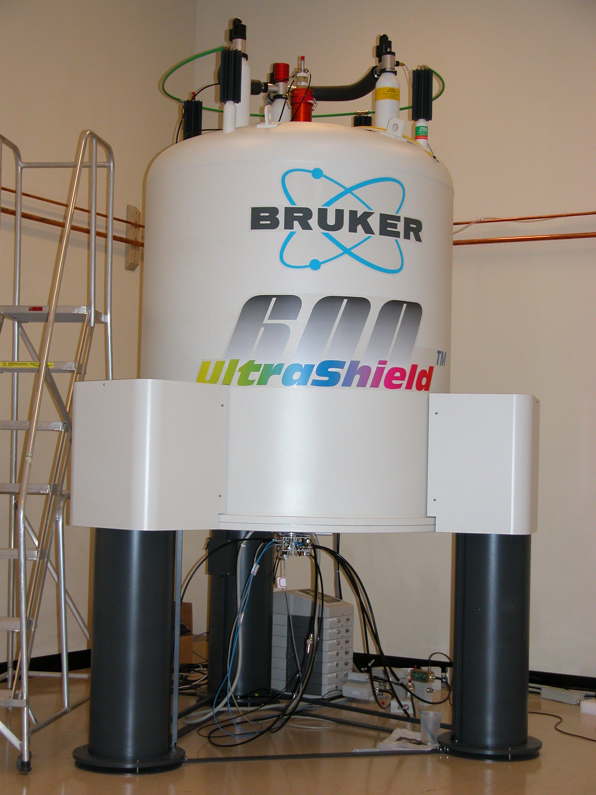
Photo by Shaoxiong Wu, Lake Taheo, CA, October, 2003
|